


THE SET
This unit isn’t a simple LED scanner but a complete system which integrates an audio board, a 433MHZ remote controller, two sound filter, the PIR sensor, a keyboard and the cables to connect all the components, battery, electronic set installed in your dashboard and the other boards of this set.
You will receive a complete unit, with demo mode, random phrases mode, laser ready (interface ready with ZA pods) updatable firmware and yes, of course different effect light like in the show.
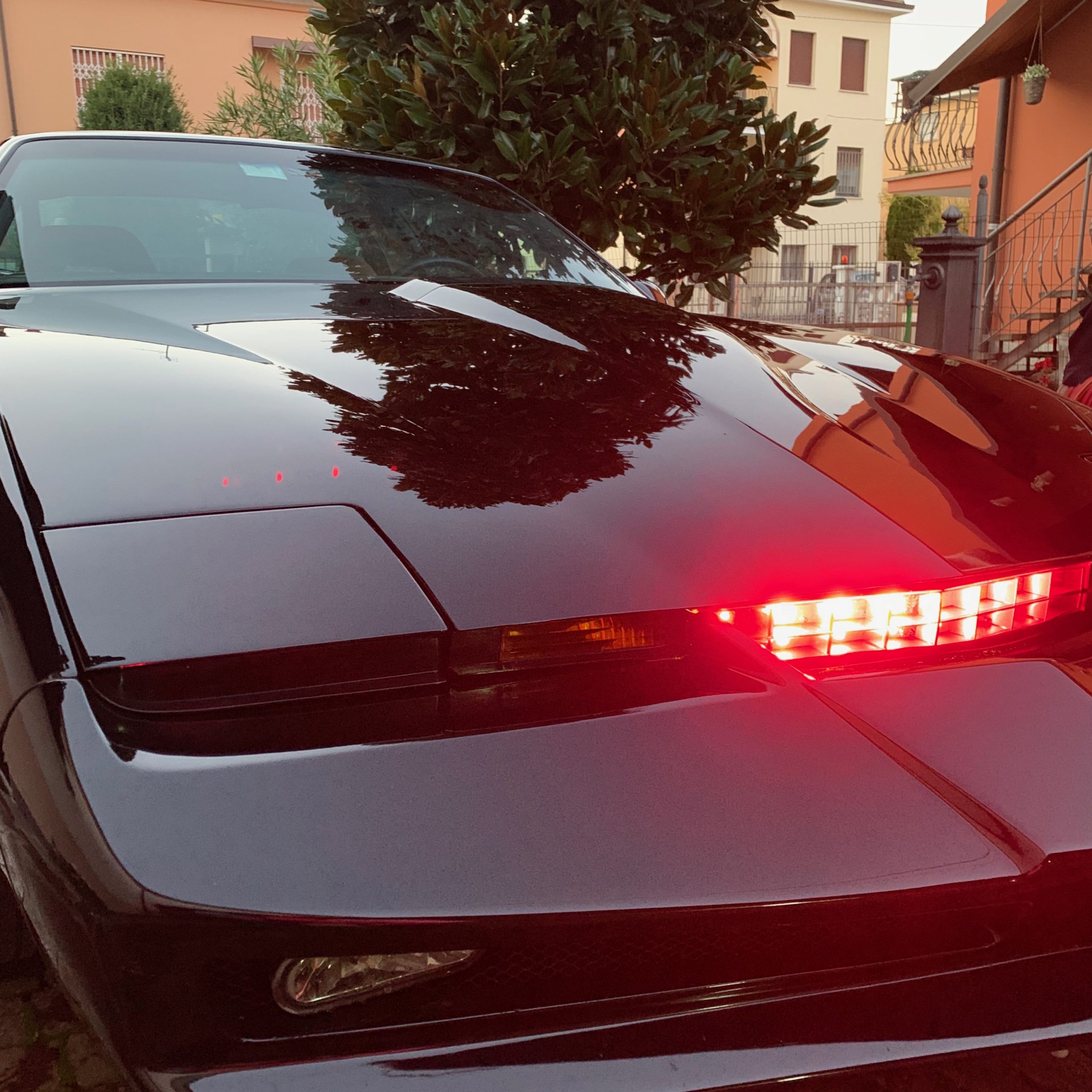
THE ALUMINIUM BAR
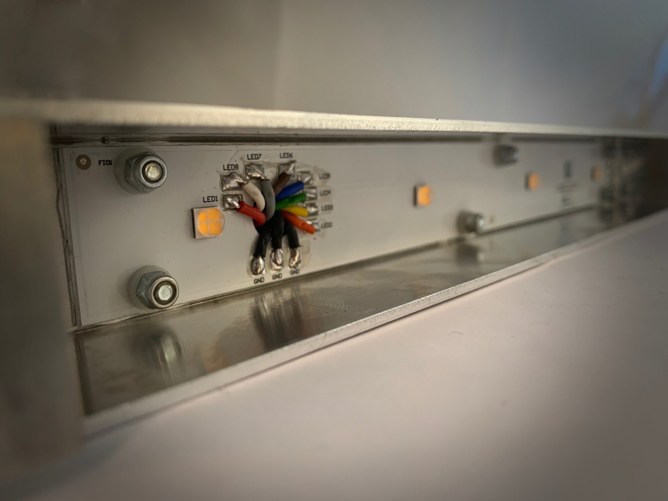
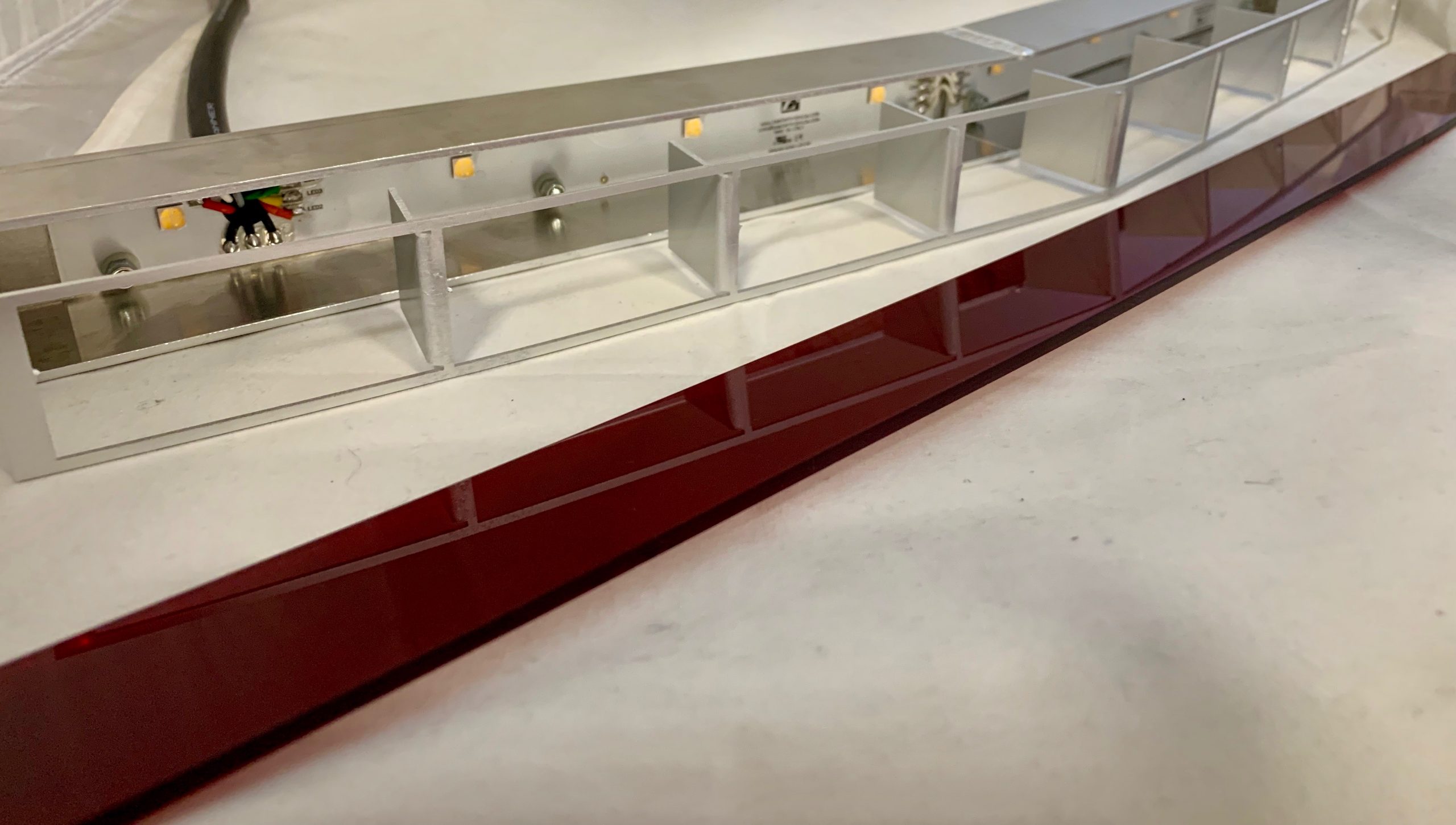
The scanner is built with an aluminium bar divided into 2 pieces soldered in the center with the classic V form molded with hood V. Inside the bar there is the led scanner circuit; to dissipate the heat in an efficient manner the circuit as been developed with a PCB metal core instead of vetronite. This procedure, more complex and expensive permits a better heat dissipation inside the circuit through the aluminum bar .
During assembly, an external section is added for every single cell to obtain the 8 cells in the scanner bar.
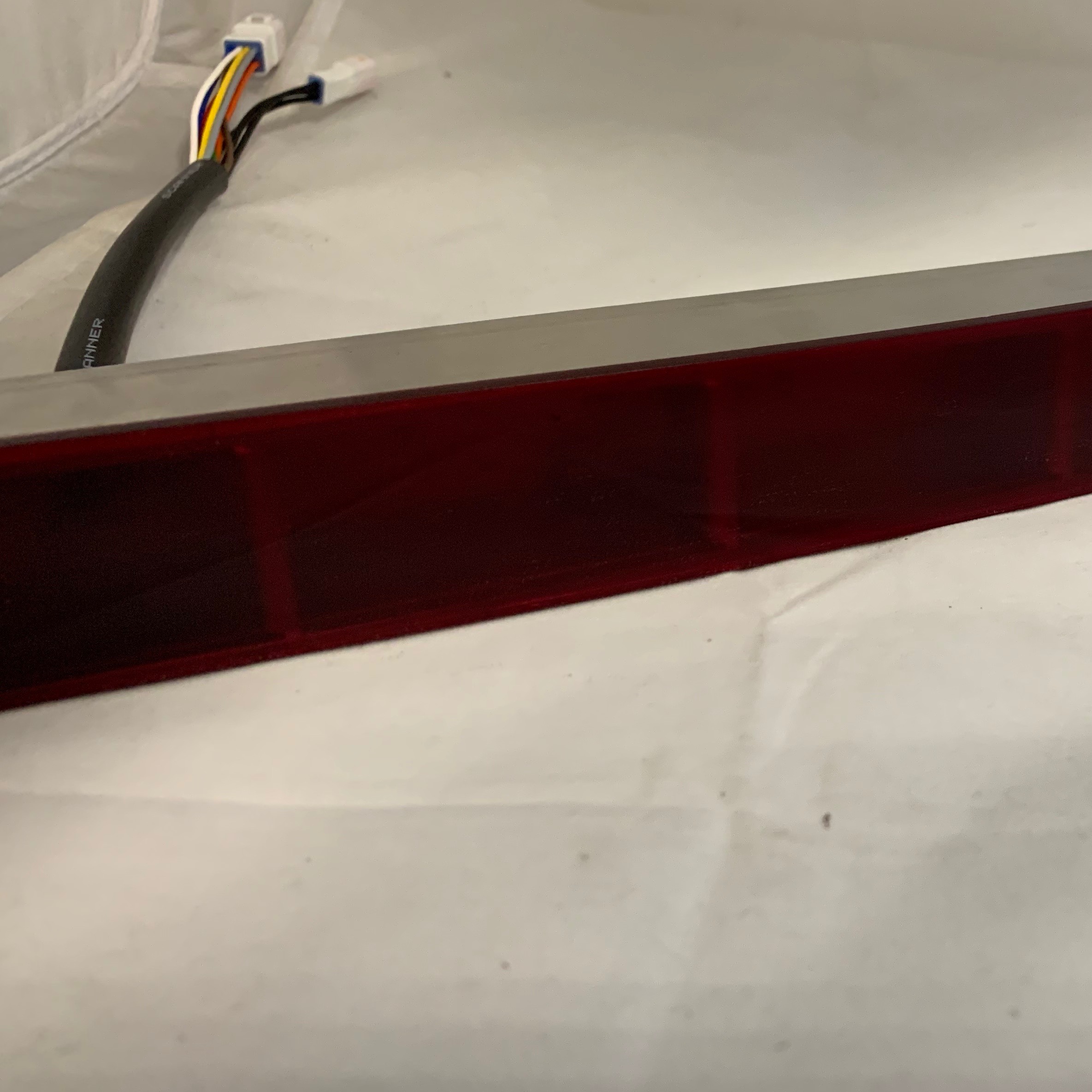
To complete the scanner a red plexi is placed in front of the bar; in the left rear of the bar, two bundles of cables exit, one of them counts 8 cables and one 3. These cables end with IP68 connectors that have to be connected with the Drivers board inside the aluminium box
The scanner works ONLY if connected to a ZA electronic set because it uses the can-bus network to obtain working information as for example the car speed, rpm and power status of the dashboard. There is no other way to make it work!
THE CABLES
All the cables within the set have automotive specifications and IP68 connectors. This to guarantee your safety and a perfect operation in every condition.
All the cables are sheathed and marked to be identified for easier connection to its component.
In order to avoid that more cables pass inside the car interior, it has been studied that the main power sits inside the engine bay. The drivers board has an integrated relay which interrupts power if the electronic set is switch off and of course it active when the dashboard is on. This also is done to avoid your battery drain during period of non-use.
From the dashboard, through the canbus network and the white DMX cable, it is sent a p on signal power, that put the scanner in a standby condition. When the dashboard is switched off from the main switch, also the relay inside the drivers board disconnects the power from the battery.
The connection to the battery can be done directly with the housing on the cable. If the housing does not fit your needs can be cutted off and replaced with a correct one.
-
•Red cable is positive (+12 VOLT)
-
•Black cable is negative (Earth, GND)
THE DRIVER BOARD
Since this board has been developed from scratch, the design has been studied in its smallest details. Tanks to the cad design it has been calculated the correct and necessary space in which this box should be placed. And precisely it is put exactly behind the right direction light near the hood latch mounting bracket, where there are the two ribs of the frame. After you have fixed the box with four screws, your box will be perfectly aligned and will never move.
The driver board, for safety and protection against bad weather is enclosed in an alluninioum box and has these inputs/outputs:
✓Power + 12 volt for board, scanner, radar, relay;
✓DMX cable for internal connection to the electronic set;
✓RELAY cable for optional laser module (not included) which can be activated pressing a switchpod button ZA;
✓RADAR cable to connect to the front PIR radar.;
✓Interface cables for the scanner bar: 11 cables in 2 IP68 connectors, one of 8 and the other of 3;
THE RELAY (LASER) CABLE
This cable is designed to activate the LASER function from inside the car with out having to use external sources.
This function is usually activated from inside the car; isn’t simple and external relays/equipment must be used. This cable which comes from the drivers board can be connected to a laser diode, usually installed on top of the scanner bar, and powered from ZA swithpod.
Thanks to the ZA electronic set, ZA switchpod buttons and this new product, the laser function will not be a nightmare anymore!
The “laser” button on the swichpod will automatically switch your button press into a relay action that is inside the driver board. The button is the 17 (P ENG on the photo), and is located on right pod (the turbo boost pod), second one from top right, next button down the white “6 RM”.
The LASER button for your pod unit, can be purchased as option, with the EXTRA 18 buttons see on the series.
WHAT IS PIR AND HOW IT WORKS IN THE SCANNER
It is a passive infrared sensor (Passive InfraRed) which measures heat from objects in front of it.
All objects with a temperature above absolute zero emit heat energy in the form of radiation. Usually this radiation isn’t visible to the human eyes because it radiates at infrared wavelengths, but it can be detected by electronic devices designed for such purpose.
The term passive in this instance refers to the fact that PIR devices, do not generate or radiate energy for detection purposes. They work entirely by detecting infrared radiation emitted by or reflected from, objects. They do not detect or measure “heat”.
When the scanner gets in standby mode the PIR sensor reads the enviornment temperature (20 seconds) which is set as default. Every variation read by the sensor, activates one or both of the following functions:
-
•scanner activation (if enabled)
-
•dashboard activation (if enalbed)
The Sound Boards: Electronic interface, remote controller, MP3, real turbine and click speed sound
This board is part of the scanner system. Is the second brain of Scanner & Sound unit. The MP3 player is used to reproduce a file when the scanner is turned on, when an event occurs through the PIR radar, or in random phrases mode.
There are 4 RCA connectors on the sound board: 3 outputs (near each other) and 1 AUX input
MAIN OUTPUT
It outputs an audio signal in high quality which can be used as in-line of an amplifier.
The sounds played from this connector are:
-
•MP3 Sound;
-
•Turbine sound;
-
•Scanner sound;
-
•Aux input sound.
SPEED OUTPUT
It outputs an audio signal in high quality which can be used as in-line of an amplifier.
The sounds played from this connector are:
-
•Click speed sound. It plays a click everytime there is a vehicle speed change. The sound is variable depending on the speed, higher the speed is faster the click is played.
SPEED SPEAKER
It outputs an audio signal in high quality which can be used to connect an independant speaker.
The sounds played from this connector is the Click speed sound. It plays a click everytime there is a vehicle speed change. The sound is variable in base of the speed, higher the speed is faster the click is played.
AUX INPUT
This RCA connector allows to input in the system an in-line sound thorugh the mixer of the sound board. This input is played by the board through the main output.
THE TURBINE
The turbine file, which cannot be changed by the user, varies with the rpms of your engine. You will no longer hear a “flat” sound, but a sound, as in real life, that continually varies according to the rpm speed of your engine.
How is it possible?
The electronic set, thanks to the CAN bus system, reads the engine rpm and adjusts the sound of the turbine every 2 milliseconds. During this operation you will not notice any delay.
If you activate the DEMO 3 mode, in the driving simulation the turbine will read the values in your RPM board and reproduce the variation, without your engine is switched on!
THE SPEED SOUND
As we saw earlier, this sound can be played in two ways, on two separate outputs:
-
•SPEED OUTPUT
-
•SPEED SPEAKER
If you want to have a very loud sound, you can use the SPEED OUTPUT output as the LINE-IN input of an amplifier.
If you wish to have a weaker sound (recommended) and you want to controll it directly from the electronics menu, connect an INDEPENDENT speaker directly to the SPEED SPEAKER output.
NO DRIVER BOARDS ON THE COCKPIT. LEGS ARE FREE!
One of the objectives of the ZA electronics has always been to simplify the installations, and to keep the cables necessary for its operation, to a minimum.
The scanners currently on the market expect that there is a sort of internal controller that provides, in addition to turning it on / off, to show the status of the scanner, and what light effect is playing.
Taking advantage of the can-bus technology of that the electronics is equipped with, the first 3 rows board, in the lower bar, fulfills this task. It has seemed logical to use this bar as it shows in the overlays, the word RADAR and SENSOR RANGE
THE STATES OF THE BAR 3 ROWS
Depending on the status of the scanner, the bar can work in the following ways
-
•SCANNER OFF: the 3 ROWS bar works as default, just as you are used to seeing it.
-
•STANDBY SCANNER: The first red LED on the ROWS 3 bar flashes. This indicates that the PIR sensor is enabled.
-
•SCANNER ON: the 3 ROWS bar plays the movement the scanner is currently doing at the moment. The internal wake effect is limited, while the outer one is perfectly regular.


Reviews
There are no reviews yet.